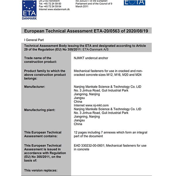
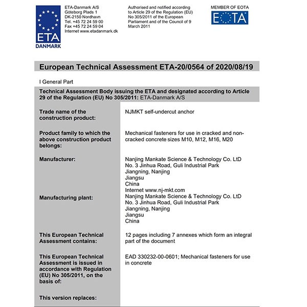
Key Features
● Consist: anchor rod, undercut lock, spacer sleeve, flat washer, anti-seismic washer, nut
● Material:carbon steel, alloy steel, stainless steel
● Anti-corrosive treatment:
galvanized steel≥5μm, applicable in indoor and outdoor surroundings
hot-dip galvanized steel≥45μm, applicable in corrosion environment
● Customers can accept engineer’s suggestions: applicable in long-lasting complex environment with NJMKT special surface treatment high-performance anti-corrosion thickness ≥10μm
Advantages
● Lock-effect anchor fixing
● Convenient installation, consistent and reliable performance, torque-turn for load-carrying-----bearing capability
● No waste holes, completely detachable for repeated use
● The anchor holes can be reused if concrete base material is not damaged
● Especially suitable for complex environment such as petrochemical industry base, ports, subways, etc.

| The average failure load, design load, and recommended load of a single anchor in large spacing and edge distance | |||||||||
| Pre-Set type C20/25 concrete base material | |||||||||
| uncracked concrete | |||||||||
| Size | M10/16 ×60 | M12/18 ×100 | M12/18 ×120 | M16/22 ×130 | M16/28 ×160 | M16/28 ×200 | M20/35 ×210 | M20/35 ×250 | M24/38 ×285 |
Effective embedment depth hef [mm] | 60 | 100 | 120 | 130 | 160 | 200 | 210 | 250 | 285 |
Drilled hole depth ho [mm] | 75 | 115 | 135 | 145 | 175 | 215 | 225 | 265 | 300 |
Drilled hole dia. do [mm] | 16 | 18 | 18 | 22 | 28 | 28 | 35 | 35 | 38 |
| Average failure load | |||||||||
Tensile force 0°[kN] Nu | 31.4 | 67.4* | 67.4* | 100 | 125.6* | 125.6* | 196* | 196* | 282* |
Shear force 90°[kN] Vu | 27.8* | 40.4* | 40.4* | 75.4* | 75.4* | 75.4* | 117.6* | 117.6* | 169.2* |
Design load | |||||||||
Tensile force 0°[kN] NRd | 14.5 | 44.9 | 44.9 | 46.3 | 83.7 | 83.7 | 130.7 | 130.7 | 188 |
Shear force 90°[kN] VRd | 18.5 | 26.9 | 26.9 | 50.2 | 50.2 | 50.2 | 78.4 | 78.4 | 112.8 |
recommended load | |||||||||
Tensile force 0°[kN] Nu | 10.4 | 32.1 | 32.1 | 22.1 | 59.8 | 59.8 | 93.4 | 93.4 | 134.2 |
Shear force 90°[kN] Vu | 13.2 | 19.2 | 19.2 | 35.9 | 35.9 | 35.9 | 56 | 56 | 80.6 |
Base material size, minimum spacing and edge distance | |||||||||
Min.spacing smin [mm] | 60 | 100 | 100 | 130 | 160 | 160 | 250 | 250 | 285 |
Min.edge distance cmin [mm] | 60 | 100 | 100 | 130 | 160 | 160 | 250 | 250 | 285 |
Min. base material thickness hmin [mm] | 120 | 200 | 200 | 260 | 320 | 320 | 500 | 500 | 570 |
Installation torque tinst [mm] | 40 | 60 | 60 | 100 | 140 | 140 | 300 | 300 | 500 |
| The average failure load, design load, and recommended load of a single anchor in large spacing and edge distance | |||||||||
| Pre-Set type C20/25 concrete base material | |||||||||
| cracked concrete | |||||||||
| Size | M10/16 ×60 | M12/18 ×100 | M12/18 ×120 | M16/22 ×130 | M16/28 ×160 | M16/28 ×200 | M20/35 ×210 | M20/35 ×250 | M24/38 ×285 |
Effective embedment depth hef [mm] | 60 | 100 | 120 | 130 | 160 | 200 | 210 | 250 | 285 |
Drilled hole depth ho [mm] | 75 | 115 | 135 | 145 | 175 | 215 | 225 | 265 | 300 |
Drilled hole dia. do [mm] | 16 | 18 | 18 | 22 | 28 | 28 | 35 | 35 | 38 |
| Average failure load | |||||||||
Tensile force 0°[kN] Nu | 22.1 | 47.5 | 62.4 | 70.4 | 96.1 | 125.6* | 144.6 | 187.7 | 228.5 |
Shear force 90°[kN] Vu | 27.8* | 40.4* | 40.4* | 75.4* | 75.4* | 75.4* | 117.6* | 117.6* | 169.2* |
| Design load | |||||||||
Tensile force 0°[kN] NRd | 10.2 | 22 | 28.9 | 32.6 | 44.5 | 83.7 | 66.9 | 86.9 | 105.8 |
Shear force 90°[kN] VRd | 18.5 | 26.9 | 26.9 | 50.2 | 50.2 | 50.2 | 78.4 | 78.4 | 112.8 |
| recommended load | |||||||||
Tensile force 0°[kN] Nu | 7.3 | 15.7 | 20.6 | 23.3 | 31.8 | 59.8 | 47.8 | 62.1 | 75.6 |
Shear force 90°[kN] Vu | 13.2 | 19.2 | 19.2 | 35.9 | 35.9 | 35.9 | 56 | 56 | 80.6 |
| Base material size, minimum spacing and edge distance | |||||||||
Min.spacing smin [mm] | 60 | 100 | 100 | 130 | 160 | 160 | 250 | 250 | 285 |
Min.edge distance cmin [mm] | 60 | 100 | 100 | 130 | 160 | 160 | 250 | 250 | 285 |
Min. base material thickness hmin [mm] | 120 | 200 | 200 | 260 | 320 | 320 | 500 | 500 | 570 |
Installation torque tinst [mm] | 40 | 60 | 60 | 100 | 140 | 140 | 300 | 300 | 500 |
● The values are suitable for: correct installation, no influence of spacing and edge distance, minimum base material thickness.
● All the data applies in C20/25 concrete base material. If the base material grade changes, the corresponding concrete influence coefficient will needs to be increased.
● The * part in the table is steel failure control.
● The material of all the anchors in the table is alloy steel, grade 8.8.
● Design load: including material partial factor, but not including overall partial factor.
● Recommended load: including not only material partial factor, but also including overall partial factor 1.4.
● If your NJMKT Dismountable Anchor(Mechanical Anchors) with special material and specification is not listed in this table, please contact our engineer for advice.
● All basic anchor data in this table is given according to 2013 ETAG001 and Appendix. The partial factor in the load application must be in accordance with national regulation.


